The aortic valve is a tri-cuspid valve, hence it consists of 3 thin leaflets that move
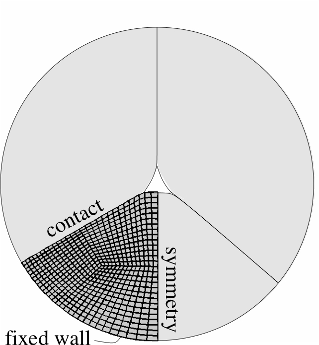
independently. In the finite-element models that are presented here symmetry conditions are being
applied for the valve. Firstly, it is assumed that all leaflets are identical and secondly
it is assumed that each leaflet is symmetric. This reduces the computational cost of the
fluid-structure interaction models considerably since only 1/6th of the solid and fluid
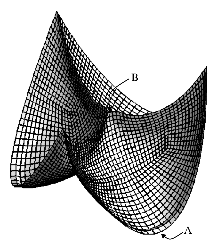
domain is used to calculate velocities, pressures and deformations. In Fig 1 only a solid
computation is performed. A Neo-Hookean material model is used to describe the solid
behaviour. The valve is fixed to the arterial wall (assumed rigid) and a pressure is
applied on the top of the valve which represents the fluid pressure in the aorta during
early diastole (valve is closing). The middle figure clearly shows how the 3 leaflets
coapt. This coaptation was described by defining a rigid-solid body contact algorithm
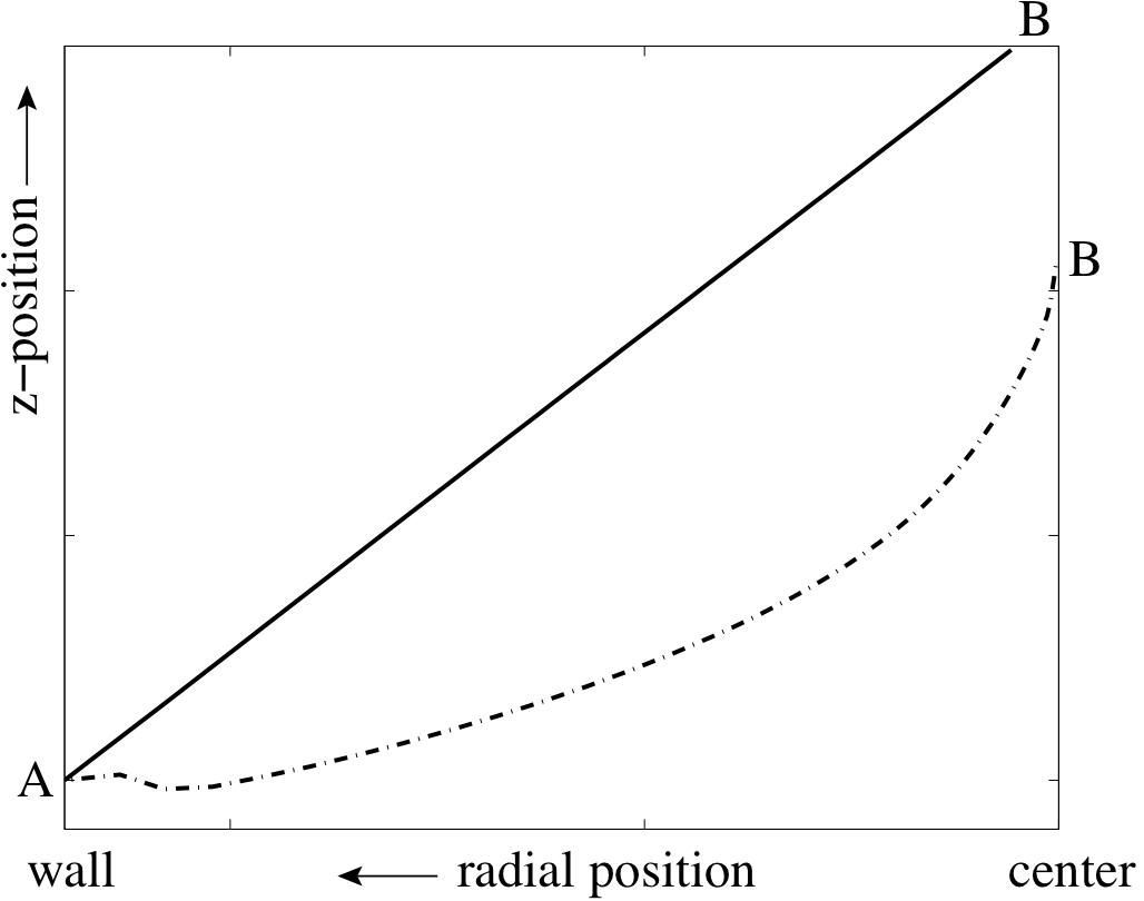
on the (contact) plane between 2 leaflets. The right picture shows the radial position
in the centre of the leaflet before and after deformation.
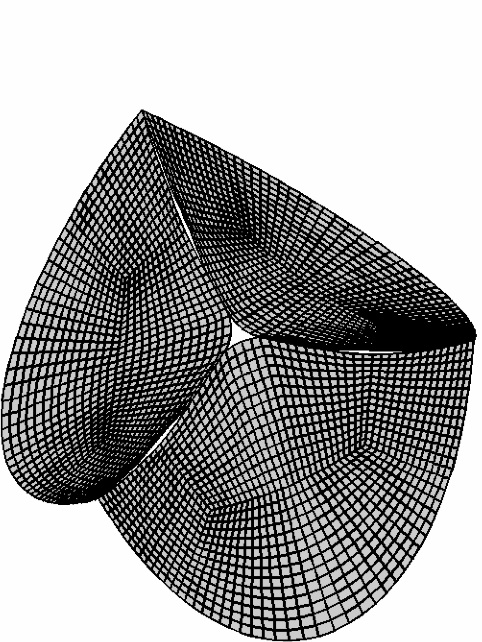
Fig. 1: The symmetry assumption for the leaflets (left). Deformed leaflet exposed to static pressure (middle) and disection lines in the undeformed and deformed state (right)
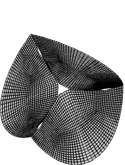
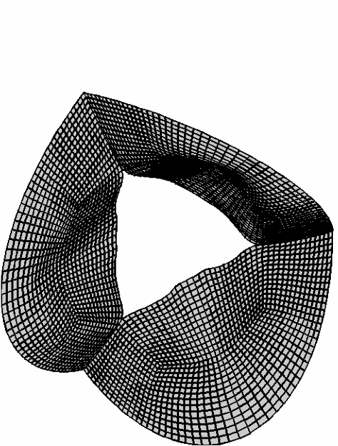
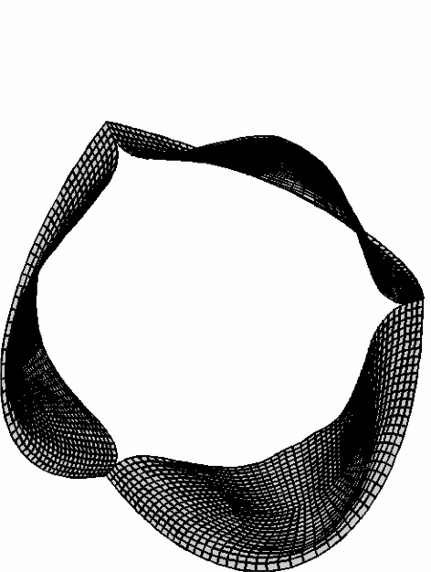
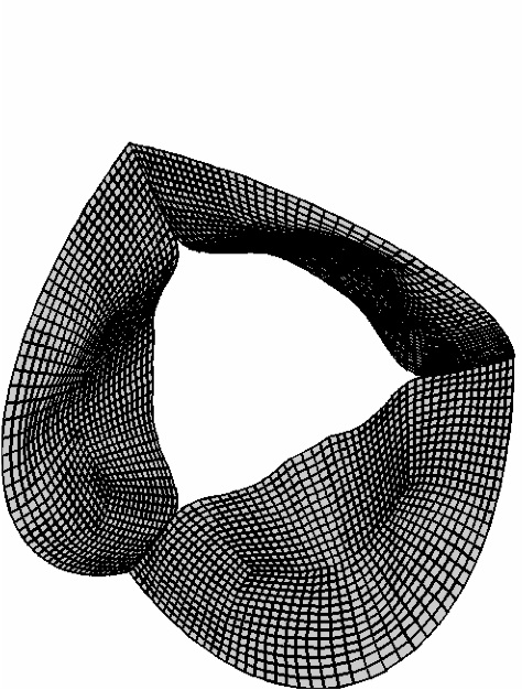
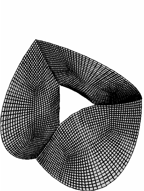
Fig. 2: Opening and closing of an aortic heart valve model in a fluid-structure interaction problem.
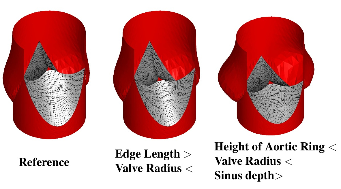
Fig. 3: Three different aortic heart valve geometries
based on five parameters.

Fig. 4: Opening behaviour of two different valve geometries: Valve with
homogeneous stiffness distribution but a longer free edge (left) and a valve
with an increased stiffness towards the belly of the valve (right).
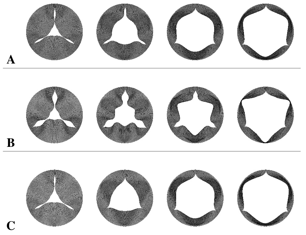
Fig. 5: Opening behaviour for three different geometries
of aortic heart valves.